
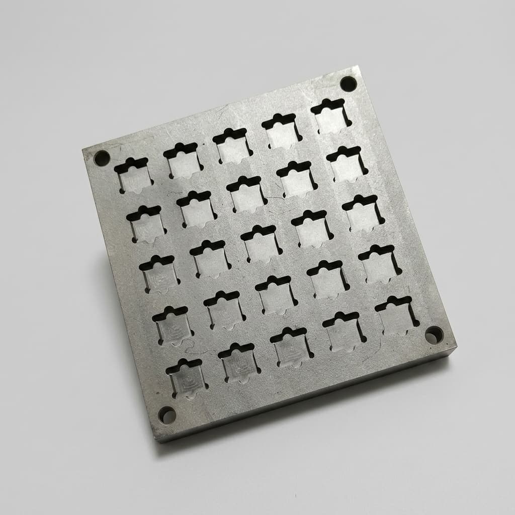
Preventing Susceptor Degradation from HCl Corrosion in 200mm SiC Epitaxy
A procurement and engineering guide to mitigating HCl/Cl2 corrosion in 200mm SiC epitaxy through dense CVD SiC coatings and optimized grain boundary structures.
The transition to 8-inch (200mm) Silicon Carbide (SiC) epitaxy has forced semiconductor fabs to adopt more aggressive growth chemistries. To achieve viable growth rates on larger wafers while controlling gas-phase nucleation, processes increasingly rely on chlorinated precursors like Trichlorosilane (TCS) and direct Hydrogen Chloride (HCl) additions. While beneficial for the epilayer, this highly corrosive environment accelerates the degradation of SiC coated graphite susceptors.
For procurement teams and process engineers, specifying a susceptor with "chemical resistance" is no longer sufficient. You must understand the microstructural vulnerabilities of the Chemical Vapor Deposition (CVD) SiC coating—specifically, how HCl attacks grain boundaries—to avoid catastrophic batch failures and premature component replacement.
This guide details the mechanisms of HCl corrosion in 200mm SiC epitaxy and provides a strict framework for sourcing corrosion-resistant susceptors in 2026.
Scope and limits, reviewed July 29, 2026: This guide is written for global procurement, process engineering, and supplier-quality teams qualifying SiC-coated graphite susceptors for 200mm SiC epitaxy lines that use TCS, direct HCl addition, or HCl/Cl₂ chamber cleaning. It is an RFQ and incoming-inspection framework, not a substitute for OEM recipe limits, coupon corrosion testing, SEM/SAM acceptance records, or chamber-specific process qualification.
If you are already scoping a high-HCl 200mm program, compare your drawings and gas exposure against our CVD SiC coated susceptor capability, then contact the technical team for an RFQ review.
The 200mm Corrosive Environment
Epitaxial growth using TCS at temperatures exceeding generates significant HCl byproducts. In this environment, any porosity or weak grain boundaries in the CVD SiC coating will be rapidly etched, exposing the underlying isostatic graphite to chemical attack and catastrophic particulate generation.
1. The Mechanism of HCl Attack: Grain Boundary Corrosion
Silicon Carbide is intrinsically highly resistant to chemical attack. However, CVD SiC coatings are polycrystalline. The boundaries where individual SiC crystals (grains) meet are inherently weaker and contain more structural defects than the bulk crystal.
During high-temperature epitaxial growth or chamber cleaning cycles (often utilizing pure HCl or Cl₂ gas), these grain boundaries become the primary vector for corrosion:
- Preferential Etching: Hot HCl gas preferentially etches the disordered atoms at the grain boundaries.
- Pinhole Formation: Continuous etching widens these boundaries into micro-cracks and eventually pinholes.
- Substrate Exposure: Once the corrosive gas breaches the SiC barrier, it aggressively attacks the porous isostatic graphite substrate.
- Catastrophic Failure: The graphite degrades rapidly, releasing free carbon and trace metallic impurities into the chamber, which destroys the epitaxial layer's doping profile and forces immediate susceptor replacement.
Figure: The structural difference between porous coatings vulnerable to grain boundary attack and dense columnar coatings that block HCl penetration.
2. Low-Temp vs. High-Temp CVD SiC
The vulnerability of the coating directly correlates to the supplier's CVD process. To cut costs and speed up production, some suppliers utilize lower-temperature CVD processes that yield a porous, equiaxed microstructure. For demanding 200mm SiC epitaxy, procurement must mandate high-temperature CVD processes that form a highly dense, columnar microstructure.
| CVD Process Type | Typical Temp | Density | Porosity Risk | HCl Corrosion Resistance | TCO Impact for 200mm Epi |
|---|---|---|---|---|---|
| Low-Temp (Equiaxed) | Moderate | High (micro-cracks common) | Poor (grain boundaries etch quickly) | High TCO due to frequent part replacements and yield drops. | |
| Mid-Temp (Mixed) | Good | Medium | Moderate (suitable for 150mm standard epi) | Moderate, but unpredictable lifespan in high-HCl environments. | |
| High-Temp (Columnar) | Very High () | Zero (fully dense matrix) | Excellent (tight grain boundaries block gas) | Lowest TCO; ensures stable 200mm wafer yields over 100+ runs. | |
| Pre-cursor (MTS) | Varies | Varies | High risk if stoichiometry is off | Low, prone to free silicon attack | Unacceptable for precision epitaxy environments. |
| SiC / TaC Hybrid | Ultra High | Zero | Maximum (TaC layer prevents etching entirely) | Highest initial cost, justifiable only for extreme corrosive processes. | |
| Solid SiC (No Graphite) | Solid | Zero | Exceptional | Extremely high cost, poor thermal uniformity compared to graphite. |
3. Engineering and Procurement Checklist
When sourcing susceptors for an advanced 200mm SiC epitaxy line utilizing TCS or high HCl flows, procurement and supplier-quality teams must align on stringent metrics. Use this checklist to vet your supplier's coating technology:
- Coating Density Certification: Request Scanning Electron Microscope (SEM) imaging of the coating cross-section to verify a dense, columnar microstructure rather than a porous one.
- CVD Process Temperature: Confirm the CVD process operates at high enough temperatures () to guarantee high crystallinity and tight grain boundaries.
- Purity & Outgassing: Verify the underlying isostatic graphite meets 5N+ (99.999%) purity (compliant with T/CASAS standards) to prevent catastrophic contamination if a pinhole does form.
- Coating Thickness Uniformity: For 200mm pockets, ensure coating thickness remains uniform (typically 80-120 ) across the stepped edges to prevent localized stress and cracking.
- Defect Inspection (SAM): Ensure the supplier uses Scanning Acoustic Microscopy (SAM) to detect sub-surface voids or delamination risks before shipping.
- Supplier Communication & Specs: Clearly define the maximum acceptable pinhole density (e.g., <0.1/\text{cm}^2) and specify the operating gas environment (TCS/HCl concentration) in the initial RFQ to align expectations.
- Failure Risk Mitigation: Require a Certificate of Analysis (CoA) for every batch, detailing the coefficient of thermal expansion (CTE) match between the specific graphite lot and the SiC coating.
4. Frequently Asked Questions (FAQ)
Q: Can we simply specify a thicker SiC coating to prevent HCl from reaching the graphite?
A: No. Merely increasing thickness on a low-temperature, porous coating will not prevent HCl penetration; the gas will still travel down the weak grain boundaries. Furthermore, excessively thick coatings increase thermal mismatch stresses, significantly raising the risk of coating delamination on 200mm susceptors.
Q: How does HCl addition affect the susceptor compared to Hydrogen (H2) etching?
A: While H2 etching primarily causes gradual thinning across the entire susceptor surface, HCl is highly reactive and preferentially attacks crystalline defects and grain boundaries. This leads to deep, localized pitting (pinholes) that can breach the coating much faster than uniform H2 wear.
Q: Are there specific handling protocols to prevent chemical attack?
A: Yes. Mechanical scratches from tweezers or rough wafer handling create localized defects in the SiC coating. In an HCl-rich environment, these scratches become immediate nucleation sites for severe corrosion. Strict cleanroom handling protocols are mandatory.
Q: What is the expected lifespan of a SiC coated susceptor in a 200mm TCS process?
A: Lifespan varies drastically based on coating density. A standard low-temp porous coating may fail after 30-50 runs due to HCl penetration. Conversely, a high-temp, dense columnar coating can often exceed 150+ runs, significantly lowering the Total Cost of Ownership (TCO) despite a higher initial procurement cost.
5. Sources and References
- Process-Structure-Property Correlation in CVD-SiC Coatings of Graphite Susceptors: Open-access study on how CVD process parameters and coating microstructure affect coating quality for graphite susceptors. Review open-access study
- Semi-Cera Susceptor Technology: Technical details on balancing thermal expansion and preventing HCl gas attack in high-temperature epitaxial growth. Read Engineering Guide
- SGL Carbon SIGRAFINE SiC coating: Technical overview on CVD SiC coating properties, emphasizing the importance of high density and CTE matching for corrosion resistance. Review SiC coating overview
Upgrade Your 200mm Susceptors
Don't let inferior, porous CVD coatings limit your 8-inch SiC epitaxial yield. Our CVD SiC coated susceptors utilize high-temperature CVD processes to deposit fully dense, columnar SiC coatings designed specifically to withstand aggressive HCl and TCS environments. Contact our technical team to review your process parameters and request a custom RFQ.
Author

More Posts
SiC Coated Graphite vs. Solid SiC Components: A Procurement & Engineering Guide
Compare SiC coated graphite vs. solid SiC for semiconductor components: purity, plasma resistance, machinability, lifespan, RFQ criteria, and tradeoffs.
Preventing Wafer Slip and Bow in 200mm SiC Epitaxy: Susceptor Specifications
A comprehensive engineering and procurement guide to mitigating wafer slip, bow, and warp in 200mm SiC epitaxy through advanced SiC coated graphite susceptor design.
SiC Susceptor Lifespan: How H2 Etching Impacts Epitaxy Yield and TCO
Learn how H2 etching shortens SiC susceptor lifespan, raises epi defect risk, and changes TCO. Use Sicgraphite's checklist to qualify CVD SiC coatings.