
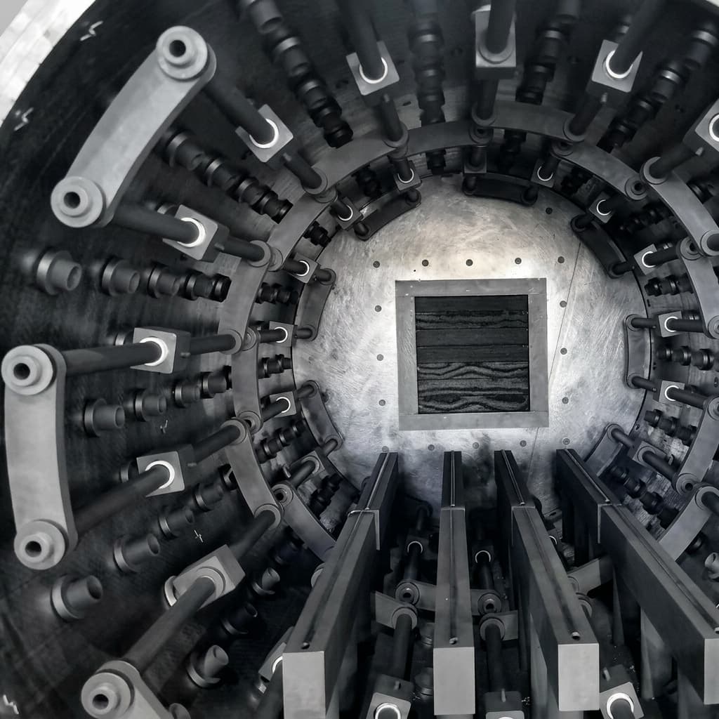
Graphite Heating Elements in High-Temperature Vacuum Furnaces: Meander vs. Cage Geometry, Arcing Prevention, and Creep Resistance
Compare graphite heating elements for vacuum furnaces: meander vs. cage, arcing risks, creep, and terminal design. Build your RFQ with an acceptance checklist.
Specify graphite heating elements in high-temperature vacuum furnaces by geometry, grade-specific resistance, atmosphere, supports, and terminal interfaces. Meander panels suit rectangular or separately zoned surfaces; cylindrical cages suit surrounding a circular workload. Neither geometry alone establishes temperature uniformity, arc immunity, or service life.
This engineering and procurement guide provides thermal process engineers, equipment builders, and procurement teams with a practical framework for selecting element geometries (meander ribbon vs. cylindrical squirrel-cage vs. multi-segment tube), preventing glow-discharge arcing under Paschen's law, designing creep-resistant supports, and structuring an RFQ package with verified acceptance criteria.
Review our dedicated high-purity graphite heaters catalog and vacuum furnace hot zone solutions for standard and custom manufacturing specifications.
Published and reviewed: October 31, 2026. Scope: Global engineering and procurement guidance for graphite resistance heaters in vacuum and compatible inert-gas furnaces, including semiconductor hot zones. Process temperature, vacuum range, gas chemistry, and contamination limits must be specified for each furnace. Nitrogen suitability depends on the workload and process chemistry; hydrogen, halogens, and reactive atmospheres require a separate compatibility review.
Evidence and limitations: This is a design-review and RFQ framework, not a furnace qualification report. The comparison tables express engineering selection criteria; the worked calculation uses hypothetical inputs. Product images illustrate component arrangements. Grade datasheets, OEM-approved drawings, and application testing establish acceptance limits. Revisit this guide when a cited standard, material grade, atmosphere, or furnace design changes, and review it again within 12 months.
Engineering boundary: Review the power supply, pump-down and backfill profiles, electrical clearances, and insulation pack together. Material purity alone cannot prevent discharge during changing pressure or outgassing conditions.
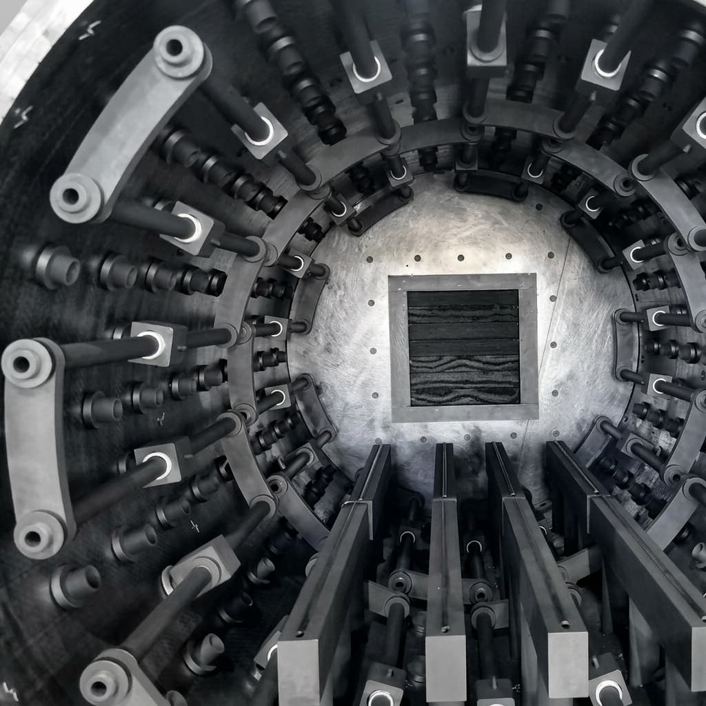
Figure 1: Illustrative furnace hot-zone assembly showing the arrangement of supports and connection hardware. Material grade, purity, and dimensions require separate documentation.
1. Electrical Resistivity Dynamics: The NTC-to-PTC Transition
Synthetic graphite can show decreasing resistivity during initial heating (negative temperature coefficient, NTC), followed by increasing resistivity at higher temperatures (positive temperature coefficient, PTC). The minimum and the size of the change depend on grade, orientation, and temperature. Obtain the proposed grade's resistivity-versus-temperature curve instead of applying a universal percentage correction.
Cold resistance is a baseline, not the full power-supply specification
ASTM C611-21 addresses room-temperature electrical resistivity. It does not prescribe a heater grade, resistivity range, or operating-temperature resistance. Specify specimen orientation, batch traceability, and agreed acceptance tolerances separately.
For a uniform current path:
Here is resistance in , is resistivity in , is path length in metres, and is conducting area in square metres. For varying sections, calculate each section and combine the actual series/parallel network. Include terminal contact resistance separately.
At fixed voltage, falling resistance increases current and power. Check transformer taps, current limiting, and controller behavior at the minimum resistance as well as the cold and hottest conditions. A cold-resistance match alone cannot establish hot-zone uniformity.
Worked RFQ example: a resistance match can still exceed the current limit
Hypothetical inputs, not measured grade data: a uniform path has , , and room-temperature resistivity . Then . At a nominal 20 kW, and .
Assume solely for this sensitivity example that resistance falls by 20% to :
| Control condition | Resistance | Voltage | Current | Power |
|---|---|---|---|---|
| Nominal room-temperature calculation | 0.20 Ω | 63.25 V | 316.23 A | 20.00 kW |
| Hold 20 kW as resistance falls | 0.16 Ω | 56.57 V | 353.55 A | 20.00 kW |
| Hold the original voltage as resistance falls | 0.16 Ω | 63.25 V | 395.28 A | 25.00 kW |
Procurement decision: a 330 A supply would support the nominal calculation but could not deliver 20 kW at the assumed lower resistance. Ask the supplier for the grade curve and operating envelope before accepting an electrically interchangeable replacement. These voltages are arithmetic results, not discharge limits.
2. Electrical Arcing & Paschen's Law in Vacuum Thermal Zones
Discharge can occur between element legs, across a contaminated insulator, or from an element to a grounded shield. Review each potential difference and clearance, including phase-to-phase and element-to-ground paths.
The Paschen minimum depends on pressure multiplied by gap
For an idealized gas gap, breakdown voltage depends on the product of pressure and gap , as explained in KEYENCE's Paschen-law overview. A simplified form is:
In this equation, and are gas-dependent coefficients with consistent units, and represents secondary electron emission at the electrode. This is unrelated to the conductor area in Section 1.
Breakdown voltage
  ^
  | \                       /
  |  \                     /
  |   \______ minimum ____/
  +----------------------------> pressure × gap (p × d)
       Qualitative only; no numerical operating limits
A minimum in cannot be converted into a universal chamber-pressure interval without specifying the gap and gas. Hot gas, local electric fields, surface deposits, and electrode condition further limit this simplified model. The cited overview explains the relationship in air; it does not qualify argon, nitrogen, or hot graphite furnace hardware.
Design and operating controls to reduce discharge risk
- Voltage and clearance review: Low-voltage, high-current designs may reduce discharge risk, but no generic 60–80 V ceiling guarantees arc-free operation. Have the furnace OEM approve peak and transient voltages, gaps, insulation paths, and operating conditions.
- Pump-down and backfill interlocks: Define a validated heating-permission envelope for the actual gas, pressure, temperature, and voltage. Verify behavior during outgassing, pressure excursions, gauge faults, cooling loss, and power trips. Do not infer permission from a single generic vacuum setpoint.
- Protected insulators: Select standoffs and feedthroughs for their local temperature, atmosphere, and electrical duty. Shield insulating surfaces from conductive deposits and provide access for inspection and cleaning. Ceramic selection alone does not establish assembly performance.
3. High-Temperature Creep and Mechanical Sagging
High short-term strength does not establish resistance to time-dependent deformation. Mersen's heat-treatment brochure discusses graphite hot zones, temperature-dependent behavior, and material selection. Its general guidance does not establish creep life for a particular heater geometry.
For creep assessment, specify grade, orientation, temperature, mechanical stress, unsupported length, and dwell time. Request applicable deformation data or a qualification test. There is no universal cycle count or sag allowance suitable for every furnace.
Unsupported horizontal spans vs. vertical hanging
- Horizontal ribbons: Shorten unsupported spans where possible. Define the maximum permitted displacement from the minimum remaining electrical clearance and workload envelope, then inspect against that limit.
- Vertical suspension: Hanging elements can reduce bending from self-weight, but tensile stress, attachment loads, and thermal movement still require review. Suspension does not remove creep or fracture risk.
- Sliding supports: Allow controlled thermal movement without binding. Review support materials, contact locations, electrical isolation, and local cooling effects together; a conductive graphite support must not bridge separate electrical potentials.
Meander turnaround                 Terminal interface
  sharp notch -> local stress        fastener / preload system
  smooth radius -> review current    contact pad + approved interlayer
                   and stress        electrode + thermal movement allowance

Radius, support spacing, and joint stack: per approved assembly drawing.
4. Geometry Architecture: Meander vs. Squirrel Cage vs. Tubular
The table is a selection framework, not a set of tested performance rankings. Compare alternatives at the same workload, temperature, gas, power, and duty cycle. Geometry alone cannot determine watt density, uniformity, price, or lifetime.
| Evaluation metric | Meander slotted panel | Cylindrical squirrel cage | Segmented tubular / rod | Carbon-carbon (C/C) ribbon |
|---|---|---|---|---|
| First geometry to evaluate | Rectangular surfaces or separately controlled zones | Circular workload with surrounding radiation | Localized or modular heating paths | Assemblies where low mass or mechanical loading motivates a composite review |
| Electrical sizing | Review web area and turnaround current crowding | Establish the actual slotted current path and segment connections | Confirm series/parallel connections and joint resistance | Obtain directional resistivity for the fiber architecture |
| Support question | What limits bending of each horizontal span? | What supports the slotted cylinder and accommodates expansion? | What limits rod bending and joint movement? | Are fiber direction and attachment loads compatible? |
| Uniformity evidence | Loaded-zone mapping with the proposed zoning | Loaded-zone mapping, including end effects | Mapping near gaps and terminals | Mapping with the intended layup and supports |
| Local failure features | Slot roots, thin webs, and mounting notches | Slot ends, end rings, and segment joints | Contact joints and unsupported lengths | Cut edges, holes, attachments, and possible delamination |
| Drawing review | Slot width, web thickness, radius, and flatness | Wall thickness, concentricity, slot pattern, and handling provisions | Alignment, joint fit, and contact surfaces | Layup orientation, section thickness, and machining details |
| Maintenance scope | Check whether one panel can be replaced independently | Establish monolithic versus segmented replacement access | Define which modules are replaceable and resistance-matched | Confirm repair policy and availability of qualified spares |
| Cost comparison | Quote complete panel, supports, and installation | Include assembly, shipping protection, and lifting fixtures | Include every electrical joint and spare module | Include layup, densification, machining, and qualification |
| Life acceptance | Agree deformation, cracking, and resistance-drift limits | Agree slot/end-ring and joint inspection limits | Agree joint and resistance-drift limits | Agree deformation and laminate inspection limits |
Meander slotted geometry: specify the radius, then verify it
At slot turnarounds, small radii and abrupt section changes can concentrate current and mechanical stress. Specify a smooth transition and minimum remaining web on the approved drawing. Review the region using coupled electrical/thermal analysis and an agreed inspection or thermal-mapping method.
A single rule such as cannot qualify all designs: slot width, ligament width, thickness, current, and supports interact. Do not promise a universal stress factor or hotspot reduction from the radius alone.
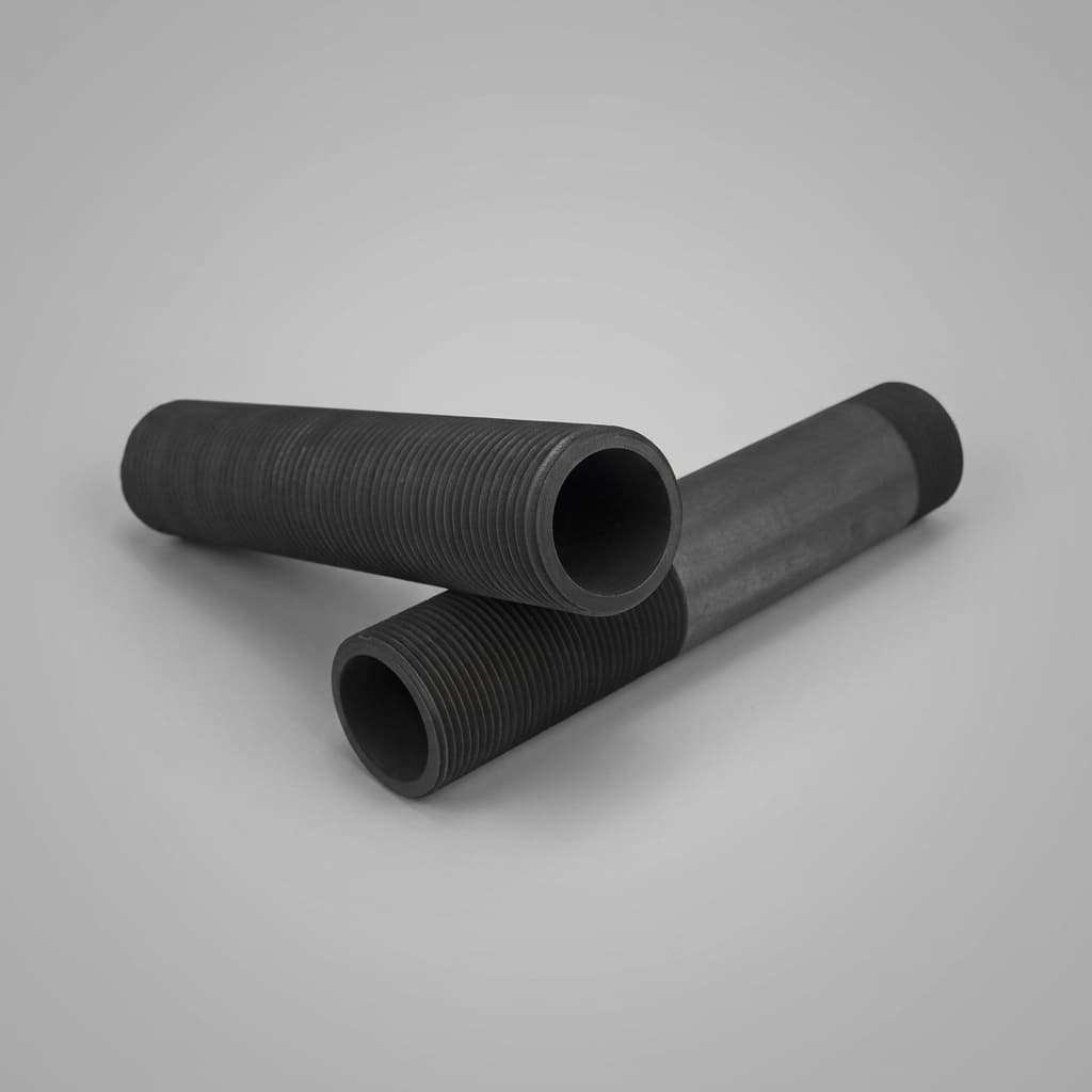
Figure 2: Threaded hollow components illustrate connection features. Meander slot geometry requires its own drawing and inspection record.
Cylindrical squirrel cage: monolithic or segmented?
Alternating longitudinal slots can create a serpentine current path around a cylindrical workload. Confirm the actual path on the electrical drawing; not every assembly called a cage uses the same circuit. Review stiffness after slotting, end-ring stresses, and handling access.
Choose segmentation based on handling, manufacturing capability, joint losses, and replacement access. Diameter alone does not establish a mandatory segment count. If C/C composite fasteners are proposed, include thread engagement, directional properties, preload, and electrical contact details in the drawing review.
5. Graphite Material Grades: Isostatic vs. Extruded vs. Molded
Specify a named grade and purification route. Forming method and purity are separate choices: “isostatic” does not mean semiconductor-pure, and purification does not establish electrical or mechanical properties.
| RFQ evidence | Isostatic graphite | Extruded graphite | Die-molded graphite |
|---|---|---|---|
| Grade identity | Supplier grade, billet, and purification route | Supplier grade, billet, and extrusion direction | Supplier grade, billet, and molding direction |
| Grain structure | Grade-specific grain size and thin-feature capability | Grain size and directional machinability | Grain size and orientation-dependent machinability |
| Density and porosity | Batch certificate and agreed limits | Batch certificate and agreed limits | Batch certificate and agreed limits |
| Cold resistivity | ASTM C611 result with orientation | ASTM C611 results in relevant directions | ASTM C611 results in relevant directions |
| Hot resistivity | Grade-specific curve covering operating temperatures | Direction-specific curves where relevant | Direction-specific curves where relevant |
| Mechanical properties | Test method, orientation, and temperature | Same evidence with billet orientation identified | Same evidence with molding orientation identified |
| Contamination acceptance | Restricted-element limits and purification certificate | Same process-specific limits; forming method does not waive them | Same process-specific limits; forming method does not waive them |
| Application approval | Confirm suitability for the actual geometry and process | Confirm anisotropy and feature size are acceptable | Confirm anisotropy and feature size are acceptable |
For room-temperature four-point flexural strength, specify ASTM C651-20 where appropriate. A room-temperature flexural result is not a tensile rating or a high-temperature creep qualification.
Ash content and elemental purity answer different questions
A bulk ash result measures residue from the specified test; GDMS or ICP analysis reports defined analytes with method-specific detection limits and sampling. A summed elemental result must identify the elements included. Do not describe a GDMS result as an ash test or treat “below detection” as zero.
Set impurity limits from the workload's contamination budget. Require sample location, purification batch, analytical method, and reporting limits. A total-impurity target alone cannot guarantee heater life or semiconductor process yield.
6. Terminal Connection Engineering: Thermal Expansion and Contact Resistance
Terminal joints deserve a separate design and inspection plan. Different expansion, uneven contact pressure, and local heat can change joint resistance during cycling. Use temperature- and orientation-specific material data for the actual joint stack.
The contact resistance cascade
Loss of contact pressure can increase resistance, creating local heating and further joint damage. Use power, , to quantify the consequence. For example, an assumed additional at 1000 A produces 100 W at the joint. This calculation illustrates sensitivity; it is not a measured failure statistic.
What the terminal drawing should define
- Pad section and cooling: Size the current-carrying area and thermal path to keep every joint component within its approved temperature limit. Verify pad temperature under the intended duty cycle.
- Contact faces and interlayers: Specify flatness, finish, cleanliness, and any approved flexible-graphite interlayer. Confirm compatibility, compression, and local current density rather than assigning a generic resistance improvement.
- Fastener and preload: Select graphite, C/C, or metallic hardware for the local thermal and mechanical conditions. Define engagement and an assembly procedure; C/C properties depend on fiber direction and do not guarantee retained preload.
- Acceptance record: Record initial joint resistance or voltage drop using an agreed method, then inspect against the OEM's thermal-cycle and resistance-drift limits. Perform maintenance only under the furnace's approved shutdown and isolation procedure.
7. Procurement & RFQ Specification Checklist
Send the same duty and acceptance package to every bidder. The checklist identifies what must be agreed; numerical limits belong in the furnace-specific drawing and purchase specification.
Phase 1: RFQ package documentation
- Atmospheric profile: Base vacuum, complete process-pressure range, gas composition and purity, outgassing stages, and pump-down/backfill sequence.
- Temperature and duty: Continuous and peak temperatures, ramp/cooling rates, dwell times, cycles, and workload geometry.
- Electrical window: Maximum and minimum supply voltage/current, AC or DC waveform, transformer taps, circuit topology, and current/power limiting.
- Material evidence: Named grade, billet orientation, density, grain size, cold resistivity, hot resistivity curve, and agreed batch tolerances.
- Purity evidence: Restricted-element table, any separate ash limit, analytical methods, sampling, detection limits, and purification/billet traceability.
Phase 2: Dimensional and mechanical acceptance
- Controlled drawings: Revision-controlled CAD and drawings defining slot radii, minimum webs, support locations, and hot/cold clearances.
- Inspection plan: Agreed slot width, web thickness, flatness, and alignment tolerances with measurement methods and datum references.
- Terminal interface: Pad geometry, contact finish, electrode cooling, fastener engagement, interlayer specification, and preload procedure.
- Handling and spares: Lifting/packing provisions, assembly sequence, replaceable segment boundaries, and electrical matching requirements for spares.
Phase 3: Pre-commissioning and in-service verification
- Cold circuit resistance: Agreed four-wire measurement temperature, contact points, and acceptance band; distinguish finished-part resistance from material resistivity.
- Electrical insulation: OEM-approved isolation and test procedure, including which electronics must be disconnected and the permitted test voltage and acceptance limit.
- Interlock challenge: Document approved pressure/gas/temperature/voltage combinations and verify heating inhibition, shutdown behavior, and sensor-fault response.
- Thermal and deformation checks: Agree loaded-zone mapping, joint-temperature limits, creep/clearance limits, and the contract-required pyrometry standard and edition, if applicable.
- Service baseline: Record initial resistance, clearances, and inspection images; set inspection intervals and replacement triggers with the OEM.
8. Frequently Asked Questions (FAQ)
What causes graphite heating elements to thin or lose mass over time?
Carbon sublimation and reactions with residual gases can remove material. Their relative importance depends on temperature, pressure, gas chemistry, and grade. Check leaks, gas purity, element temperature, and process deposits before changing power density or backfill conditions. Establish an acceptable mass-loss or resistance-drift limit through the application qualification; a generic watt-density threshold cannot establish service life.
Can a cracked graphite heating element be repaired with carbon cement?
Remove a cracked element from service for OEM assessment. A bonded joint changes electrical resistance, mechanical strength, and contamination behavior. Use only an explicitly qualified repair process; otherwise replace the affected part and confirm resistance matching and installation clearances before restarting.
When should a furnace builder evaluate C/C heaters instead of isostatic graphite?
Evaluate C/C when low mass, loading, quench forces, or damage tolerance motivate a different structure. Require layup-specific electrical, mechanical, and creep data, plus an assembly quote. Do not infer zero creep, a fixed lifetime multiplier, or a fixed cost premium from the material family.
How does furnace pressure affect allowable heater voltage?
Gas breakdown depends on pressure multiplied by gap, gas identity, and electrode conditions. Surface flashover and contamination add other failure paths. Approve voltage and heating interlocks for the actual assembly across pump-down, processing, and backfill; neither a universal pressure band nor a 60–80 V rule is sufficient.
How often should elements and terminal hardware be inspected?
Use the OEM's initial maintenance interval, then adjust it with recorded resistance drift, deposits, cracks, joint condition, and clearance changes. Reinspect after an arc, cooling fault, pressure excursion, or unusual resistance change before return to service. Use the approved cold maintenance procedure for fastener checks.
9. Engineering Action Plan
Before accepting a replacement or new heater design:
- Choose geometry for the workload: Compare radiation coverage, supports, electrical path, and replacement access using the same process duty.
- Check the complete electrical envelope: Use the proposed grade's resistance curve and verify current/power limits and assembly-specific discharge controls.
- Approve interfaces: Define slot radii, thermal movement, terminal contact behavior, and deformation/clearance limits on controlled drawings.
- Compare evidence packages: Require material and purity traceability, dimensional inspection, cold resistance, and agreed commissioning results.
For a manufacturing feasibility review, send Sicgraphite your drawing and RFQ package, including the gas/pressure cycle, temperature duty, power-supply window, quantity, and acceptance criteria. Review high-purity graphite heaters or semiconductor thermal field solutions to identify the component or assembly scope you need quoted.
Sources & References
Sources checked October 31, 2026. Public standard catalogue pages establish method identity and scope; the full standards are required when a contract invokes them. The manufacturer's brochure and introductory Paschen overview do not validate furnace-specific numerical limits. Selection tables and worked calculations above are editorial engineering frameworks, not supplier test results.
- ASTM International — ASTM C611-21: Room-temperature electrical resistivity of manufactured carbon and graphite. Supports the cold-resistivity test scope, not a universal grade range or hot resistance curve.
- ASTM International — ASTM C651-20: Room-temperature flexural strength using four-point loading. Supports identification of the flexural test method, not tensile or creep properties.
- Mersen — Heat Treatment: Graphite, Carbon Insulation and CFC Composite Solutions: Manufacturer technical brochure, especially the hot-zone discussion on PDF page 3. Supports general material-selection context; application limits require grade and assembly evidence.
- KEYENCE — Electrostatic Breakdown: Solutions: Paschen-law explanation and pressure–gap relationship. An air-gap introduction, not a hot graphite furnace operating-voltage specification.
Author

More Posts
SiC Susceptor Lifespan: How H2 Etching Impacts Epitaxy Yield and TCO
Learn how H2 etching shortens SiC susceptor lifespan, raises epi defect risk, and changes TCO. Use Sicgraphite's checklist to qualify CVD SiC coatings.

TaC vs. SiC Coated Graphite for 8-Inch SiC Crystal Growth: A Procurement Guide
Compare TaC vs. SiC coated graphite for 8-inch SiC PVT growth: thermal limits, contamination risk, lifecycle cost, RFQ checks, and supplier qualification.
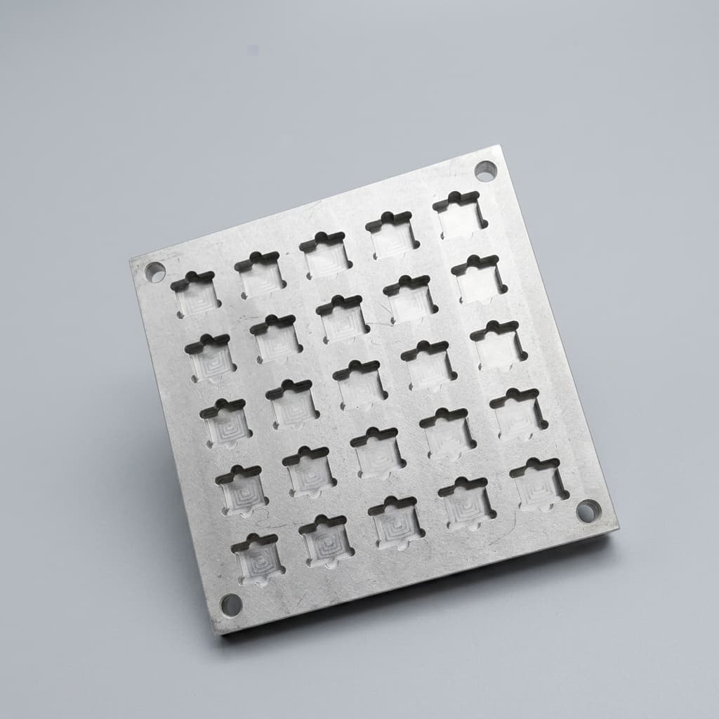
SiC-Coated Graphite Susceptors for GaN MOCVD: Engineering & Procurement Guide
Master the procurement and design of SiC-coated graphite susceptors for GaN MOCVD. Learn how CTE matching, pocket design, and coating purity impact wafer yield.