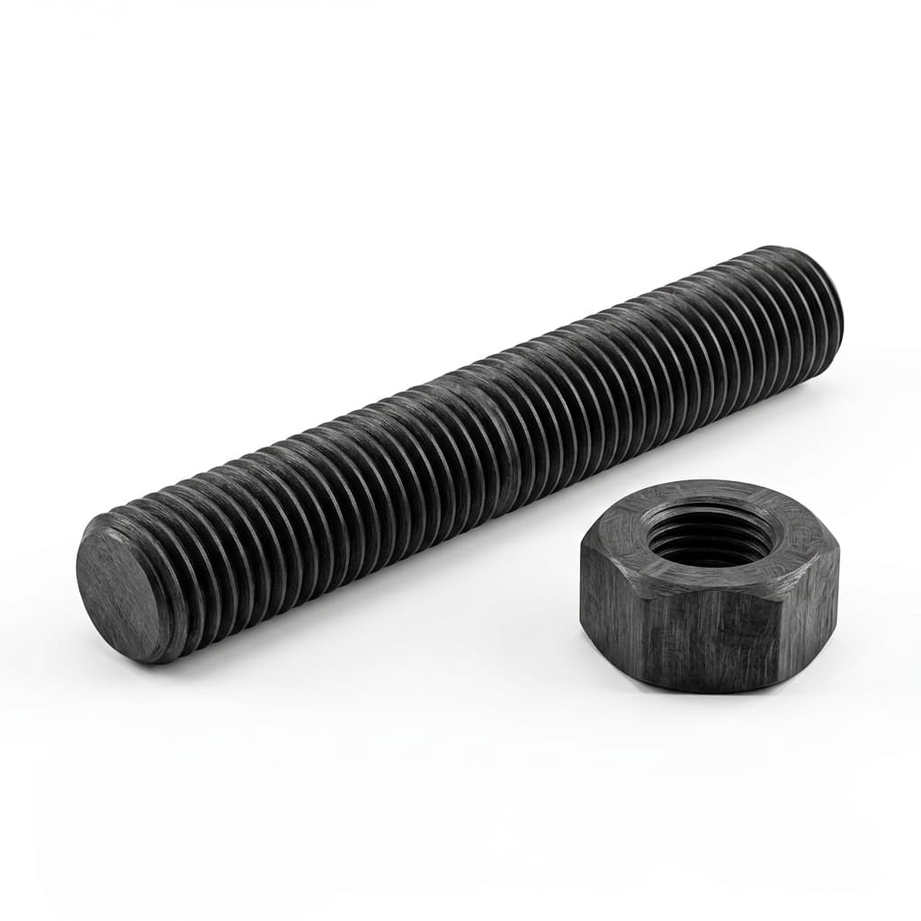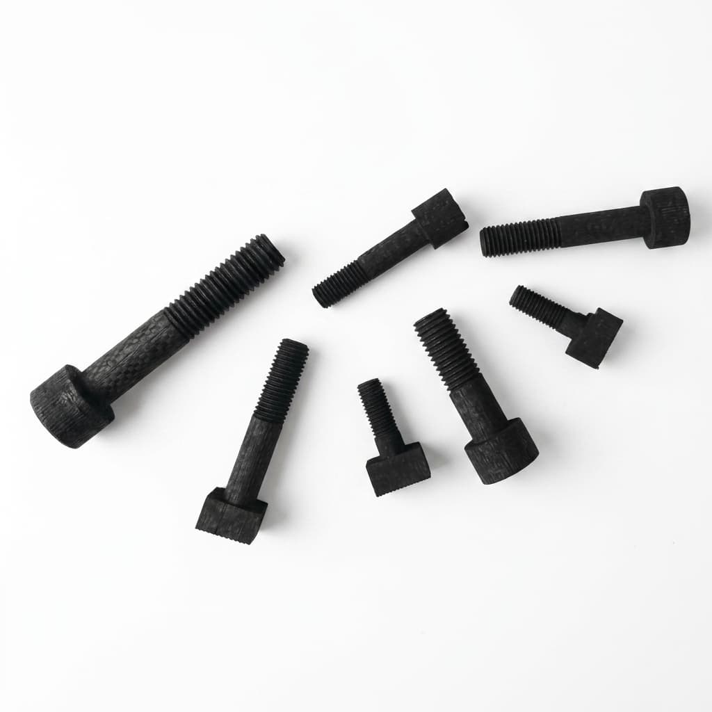
C/C Composite Bolts

Estimate torque, check thread geometry and prepare an RFQ for carbon-carbon hot-zone bolts.

Published and reviewed · By SiC Graphite. Grade and joint qualification required.

Request a drawing review

Bolt sizing & torque tool

Enter target preload and assembly K. Defaults are examples, not safe-load recommendations.

Tool range 0.01–100; not a service rating.

Tool range 0.05–0.5; not a service rating.

Geometry & service assumptions

All fields are required. Defaults are examples: M10 coarse, 60 mm bolt, 30 mm grip, 18 mm engagement, 1400°C vacuum, bare carbon; average bolt/stack CTE 1/4.5 ×10⁻⁶/K. Edit before using your own assembly data.

Tool range 10–500; not a service rating.

Tool range 1–500; not a service rating.

Tool range 1–500; not a service rating.

Tool range 20–2400; not a service rating.

Tool range -5–30; not a service rating.

Tool range -5–30; not a service rating.

Load an illustrative scenario

Ready to estimate

Set diameter, target preload and assembly K, then calculate. Geometry and temperature assumptions can be expanded on the form. Missing tested load data? Request a drawing and load review.

Bolt geometry — schematic, not to scaleClamped gripEngagementUsable bolt lengthStack
Use the actual grip and engagement from the drawing. Head shape, fillets, washers and female-thread material need separate review.
Read the method and limits

Four decisions before specifying a bolt

Choose a grade, not a generic C/C strength

Architecture, density and fiber direction vary. A public comparison sheet cannot certify the proposed bolt.

[1][2][6]

Validate the assembly load path

Nominal tensile area is only a geometric reference. Head bearing, thread stripping and the mating part may govern.

[4][7]

Qualify torque and retained preload

A target load and K give an estimate. Friction variation and the thermal cycle require separate evidence.

[3]

Treat purity as a measured requirement

Agree analytical methods and elemental limits. An ash number alone cannot establish semiconductor process suitability.

[8]
Evidence needed before a bolt assembly is released1Drawing2Grade data3Joint tests4Release
A calculator supports the drawing discussion. Only material evidence and representative assembly testing support release.

Fiber architecture and the machined load path

C/C describes a material family rather than one isotropic grade. Reinforcement and processing must be specified alongside the finished drawing. The classification reference records architecture and properties; it does not prescribe one weave for every fastener. [1][6]

Architecture review — engineering questions, not strength rankings
FeatureDecision it affectsEvidence to request
Planar / laminated reinforcementMachining can interrupt load-carrying layersOrientation drawing; head-transition and thread tests
Needled / multidirectional reinforcementThrough-thickness behavior depends on the preformFiber content, density distribution and shear test direction
3D reinforcementAdditional fiber directions do not establish a finished-thread allowableRepresentative machined-bolt tests and failure location
Coated threadsDeposition changes fit and local contactFinal coated dimensions, mating gauges and assembly trials

Estimator method, assumptions and limits

Reproducible calculations and explicit exclusions
OutputMethod and unitsWhat remains unknown
Illustrative torqueT = K × F × d; F in kN, d in mm gives N·mK calibration, allowable preload and wrench/process variation
Nominal tensile areaAₜ = π/4 × (d − 0.9382p)², in mm²Machined composite failure strength and damage
Nominal axial stressσ = 1000 × F / Aₜ, in MPaStress concentration and multiaxial stresses
Engagement ratioActual engagement / nominal diameterFemale-thread strength and local load distribution
Free thermal mismatchΔL = Lgrip × (T − 20) × (αstack − αbolt); inputs use ×10⁻⁶/KStack stiffness, thermal gradients and retained clamp load

Torque follows the generic relation discussed in NASA-STD-5020B; it supplies no C/C-specific safe preload percentage. Nominal area follows the cited geometric reference. Thermal mismatch uses a linear free-expansion model with user-entered average axial CTE over the temperature range. The tool assumes a uniform temperature, a single equivalent stack and room-temperature assembly at 20°C. [3][4][9]

Default F = 1 kN, K = 0.20 and CTE values are illustrative inputs, not material recommendations. No strength increase with temperature, fixed stripping penalty for fine pitch, universal washer prescription or safe torque band is inferred. The synchronous calculation runs locally; no server request is needed.

Metric sizing reference: coarse and selected fine pitches

Nominal geometry only — no C/C proof loads or tightening specifications
SizeCoarse pitch (mm)Coarse Aₜ (mm²)Selected fine pitch (mm)Fine Aₜ (mm²)
M61.0020.10.7522.0
M81.2536.61.0039.2
M101.5058.01.2561.2
M121.7584.31.2592.1
M162.00156.71.50167.2
M202.50244.81.50271.5
M243.00352.52.00384.4

These are selected nominal pitches, not every possible fine-pitch series or a stock-availability promise. Both the table and estimator use the same pitch-specific formula. Specify the mating tolerance, root geometry, coating allowance and under-head transition on the drawing. Steel proof loads in reference tables do not transfer to C/C. [5][4]

Bolt geometry — schematic, not to scaleClamped gripEngagementUsable bolt lengthStack
Use the actual grip and engagement from the drawing. Head shape, fillets, washers and female-thread material need separate review.

What public material data can and cannot establish

The SIGRABOND Mechanical sheet provides one identifiable comparison, not a certificate for SiC Graphite parts. Its printed revision is 2018/1.0; the listed values are typical averages. [2]

Published comparison grade versus the proposed purchased bolt
PropertySIGRABOND Mechanical sheetSiC Graphite bolt status on this page
Density1.5 g/cm³ typicalNot established; request the proposed grade and batch report
Tensile strength65 MPa typicalNot established; direction and hot test conditions required
Interlaminar shear strength11 MPa typicalNot a machined-thread stripping allowable
Purified-grade ash<10 ppm typicalNot established; agree method and elemental limits
Maximum application temperature2000°C in vacuum or inert gasNot a transferable service rating
Bolt torque / cycle lifeNot specified in this sheetMatched-joint qualification required

Do not combine the highest strength, lowest ash and highest temperature from different grades into an invented product specification. No batch certificate, retained-preload curve or service-life dataset is published here. Request those records for the offered part.

Atmosphere and coating: service conditions come first

Screening actions — not approved service envelopes
EnvironmentUnresolved riskMinimum next step
Vacuum / inertResidual oxygen, moisture, process vapors and mass lossSpecify pressure, gas purity, peak temperature, dwell and leak history
Reactive / reducing gasChemistry may attack the substrate, coating or adjacent partsReview actual gas composition and exposure with the grade supplier
Air / oxidizingCarbon oxidation; coating flaws or wear can expose carbonHold for process-specific oxidation and thermal-cycle tests
SiC coatedFinal thread fit and coating integrity after assemblyCheck a matched coated bolt/nut pair through the intended cycle
PyC treatedPore sealing alone does not establish oxidation protectionAgree treatment purpose and test it under the actual atmosphere

The public comparison-grade temperature statement applies to vacuum or inert gas. It does not establish operation in air or reactive gas. Our air-service hold at ≥400°C is a conservative review trigger, not an oxidation-rate model or a safe limit below that temperature. No universal 1600°C coating guarantee is made. [2][7]

Compare alternatives using the same duty cycle

Procurement tradeoffs — evaluate actual grades and assemblies
CandidateReason to evaluateQualification / cost question
C/C compositeLow-mass furnace hardware with directional reinforcementWill machining, densification, purification and testing justify the installed cost?
Isostatic graphiteMachined carbon hardware for a compatible load pathDo brittle features, handling and threads survive the required load and cycle?
Molybdenum / TZMRefractory metal hardware where process chemistry permitsCompare grade-specific hot strength, creep, contamination and post-cycle handling
TungstenCandidate for selected refractory applicationsCheck mass, machining cost, joining geometry and the actual atmosphere
Ceramic fastenersCandidate where electrical insulation or chemistry mattersCheck grade-specific thermal shock, mating expansion and contact stresses

This table is a purchasing framework, not a quantitative performance ranking. C/C is one candidate, supported by documented furnace uses; a final substitution requires a common test cycle and acceptance criteria. Compare total cost per qualified campaign: purchased parts, inspection, replacement labor, downtime and rejected process output. Prices and replacement intervals require a current quotation. [1][7]

Failure and maintenance review

Observed symptom → investigation → release evidence
Symptom or riskInvestigateAction before reuse
Stripped or chipped threadsActual pitch/fit, cut fibers, engagement and assembly historyQuarantine damaged parts; test a matched joint before changing preload
Head or bearing-face damageTransition radius, seating geometry, eccentric load and contact pressureReview the drawing and bearing washer; qualify the modified load path
Loss of clamp load after cyclingStack stiffness, temperature gradients and washer consolidationMeasure retained load; agree a cold inspection and retorque procedure
Erosion or coating lossAtmosphere, leaks, moisture, deposition and assembly abrasionStop reuse pending dimensional and process-compatibility review
Contamination concernsSampling, cleaning, packaging and exposed coating/substrateObtain element-level results with detection limits and lot traceability
Unexpected campaign costReplacement labor, scrap and inspection requirementsCompare alternatives with the same campaign and acceptance criteria

These are investigation prompts, not diagnoses. Establish inspection and retirement rules in the released procedure. No fixed retorque schedule, 100% failure-prevention claim or guaranteed retained-preload percentage is supported by the evidence here. [3][7]

Three worked planning scenarios

Illustrative calculations and hold decisions, not customer installations or service-life results. Load capacity remains unverified in every example.

Vacuum fixture discussion

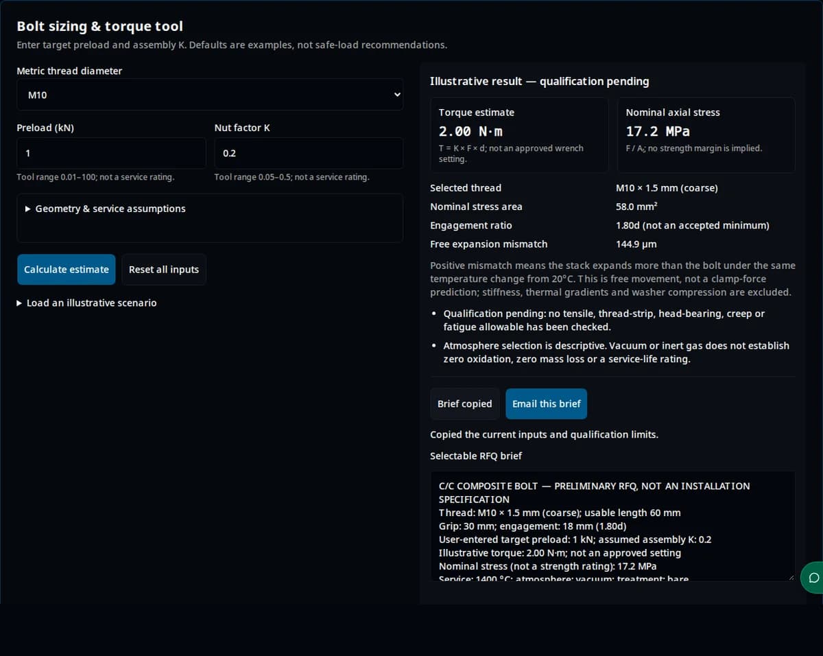
Assume M10 × 1.5, F = 1 kN and K = 0.20. T = 2.00 N·m and nominal stress ≈17.2 MPa. For a 30 mm grip, 1400°C and assumed average CTEs 1/4.5, free mismatch is 144.9 µm.

Next: verify actual CTE, head bearing, matched-thread strength and torque–tension scatter. This is not an installation setting.
Fine-pitch drawing review

Assume M12 × 1.25, F = 1.5 kN, K = 0.15 and 24 mm engagement. Nominal area ≈92.1 mm²; T = 2.70 N·m; engagement ratio = 2.00d.

Next: confirm the mating pitch and test the finished threads. Larger nominal area does not prove a larger safe load.

Air exposure at 700°C

Assume the default geometry but change atmosphere to air and temperature to 700°C. The estimator withholds torque and flags atmosphere review, including when SiC coating is selected.

Next: review a compatible material or qualify the complete coating/assembly under the actual exposure.

Reproduce the estimator example

Run captured on 1 November 2026: M10 × 1.5, preload 1 kN, K 0.20, 30 mm grip, 18 mm engagement and 1400°C vacuum, using the displayed example CTEs. Select Reset all inputs, then Calculate estimate to reproduce 2.00 N·m, 17.2 MPa nominal stress and 144.9 µm free mismatch.

C/C composite bolts estimator showing the M10 example inputs and a preliminary torque result of 2.00 N·m
Original software execution capture; cropped to the tool, with site navigation outside the frame. It demonstrates calculation reproducibility, not a physical bolt test, customer installation or allowable load.

Sources, review date and evidence limits

Links and public scopes reviewed on 1 November 2026. Standards are cited for their stated purpose, not as product certification. Confirm the contractually required edition before procurement; public summaries do not replace the full method. SiC Graphite owns this guide; see our company information and quality review scope. Review sources and assumptions again by May 2027, or sooner if specifications change. Suggested acceptance actions elsewhere on this page are engineering review recommendations.

  1. SGL Carbon — SIGRABOND material overview

    Material families and Mechanical grade for fasteners; general context, not SiC Graphite product certification.

    Source 1
  2. SGL Carbon — SIGRABOND Mechanical data sheet

    2018/1.0 printed revision. Typical comparison-grade values only; not a current batch report or a bolt allowable.

    Source 2
  3. NASA-STD-5020B — threaded fastening systems

    2021 edition, §4.3 and Appendix A: torque/preload relation, variation and thermal effects. Not a C/C furnace-bolt torque specification.

    Source 3
  4. SOLIDWORKS — nominal bolt tensile stress area

    Nominal metric geometry formula only. It does not establish composite strength.

    Source 4
  5. Nordic Fastening Group — metric fine thread table

    Nominal thread reference. Steel strength classes and proof loads in this document do not apply to C/C.

    Source 5
  6. ASTM C1836-16(2023) — C/C structure classification

    Public scope: classification by architecture and properties. Classification is not an assembly release or a universal minimum strength.

    Source 6
  7. ASTM C1783-15(2024) — C/C specification development guide

    Public scope: originally nuclear applications, with applicability to other structural uses. Not cited as a source of a fixed preload percentage or engagement ratio.

    Source 7
  8. ASTM C561-23 — ash in a graphite sample

    Public scope: residue estimation with stated limitations for purified graphite; not an element-by-element semiconductor acceptance limit.

    Source 8
  9. Rice University / OpenStax — thermal expansion

    Linear free-expansion model. Temperature-dependent, directional CTE must be supplied for the actual stack.

    Source 9

C/C composite bolt questions

Selection and evidence

What are C/C composite bolts used for?

Carbon fibers reinforce a carbon matrix. C/C threaded parts are candidates for furnace insulation and hot-zone connections where low mass and thermal expansion matter. The selected grade and joint still need qualification for the atmosphere, loads and cycle.

Is 3D weave mandatory for every bolt?

No universal architecture rule is established here. Fiber direction and through-thickness reinforcement affect machined threads and head transitions. Ask for tests on the proposed architecture and actual geometry instead of accepting a weave label as proof of strength.

What is the maximum operating temperature?

It is grade- and process-specific. The cited SIGRABOND Mechanical comparison sheet lists 2000°C in vacuum or inert gas. That value is neither a SiC Graphite batch rating nor approval for 2200–2400°C service. Obtain hot mechanical and mass-loss data for your process.

Does semiconductor service always require less than 3 ppm ash?

No universal threshold is established by the sources here. Agree element-specific limits, detection limits, sampling and cleaning with the process owner. Total ash is not interchangeable with GDMS or ICP-MS elemental results.

Sizing and assembly

Can I use the torque result as an installation setting?

No. It shows T = K × F × d for your entered target preload and assembly nut factor. It does not verify that the bolt, nut, head or substrate can carry that load. A representative torque–tension test and joint release are needed.

Why does K need to be entered?

K summarizes friction and geometry in a particular assembly. It is not the friction coefficient itself. Surface finish, lubricant, coating, bearing face and reuse can change it; no generic dry-carbon or paste value is certified here.

Does selecting fine pitch increase the allowable load?

The nominal tensile area increases for the listed fine pitch at the same diameter. Composite thread stripping depends on the cut fibers, mating thread and engagement; the tool does not turn that area increase into an allowable-load increase.

Is 1.8d a guaranteed minimum thread engagement?

No. The default 18 mm for an M10 bolt is an illustrative input. Female-thread material, head geometry, process damage and load distribution determine the required engagement. Verify it with matched-joint tests.

Service, inspection and purchasing

Can SiC coating make a C/C bolt safe in hot air?

A coating selection is not a service qualification. Thread fit, coating defects, cycling, gas composition and dwell time need review. This estimator withholds torque for air service at or above a conservative 400°C screening point; that is not an oxidation-onset or safe-below limit.

Will a flexible graphite washer absorb all thermal mismatch?

Not necessarily. A washer may distribute contact load or introduce compliance, but compression, relaxation, contamination and stack stiffness need checking. Free expansion mismatch alone cannot specify washer thickness or retained preload.

When should bolts be retorqued or replaced?

Use the released furnace maintenance procedure. Inspect cold after the agreed commissioning cycle, record thread and coating damage, and qualify any retorque procedure. No universal cycle count or retained-preload percentage is supported here.

What is needed for a useful RFQ?

Send the part and mating-thread drawings, usable length and grip, head and washer details, grade/fiber direction, operating temperature and atmosphere, load history, elemental purity requirements, inspection plan, quantity and delivery needs. Paste the tool brief as preliminary context.

Evidence for the material, assembly and purity answers: [1][2][3][4][6][7][8]

Bolt and fastener geometry examples

High-temperature carbon-carbon composite threaded bolt and fastener 1
High-temperature carbon-carbon composite threaded bolt and fastener 2
High-temperature carbon-carbon composite threaded bolt and fastener 3

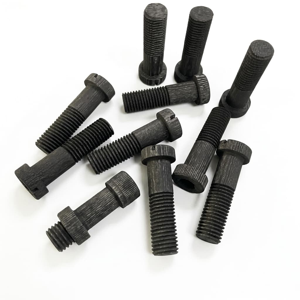
Images illustrate possible part forms. They do not establish grade, purity, dimensions, current stock or process suitability.

Request a drawing and qualification review

Use the estimator’s selectable brief or Email this brief to carry your current inputs into the inquiry. Without validated preload data, send the drawing and service conditions first.

  • Part and mating-thread drawings, head style, usable length, grip, engagement, tolerances and coating allowance.
  • Peak temperature, pressure, gas composition, dwell, thermal cycling and load history.
  • Proposed grade, fiber direction, density and direction-specific material tests.
  • Elemental impurity limits, analytical method, detection limits, sampling and cleaning/packaging plan.
  • Matched-joint torque–tension, thread, bearing and thermal-cycle acceptance requirements.
  • Sample and batch quantity, delivery date, destination, inspection records and retirement criteria.

Inquiry Email

[email protected]

Include process, product type, drawing status, purity/coating target, dimensions, quantity forecast, operating conditions, and delivery date.

Instant Chat

WhatsApp Engineering Support

Best for quick drawing checks, process fit questions, and RFQ clarification.